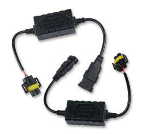
First of all, there are two major ways to fix the issue: add resistance corresponding to your bulbs, or attach a CANbus error-free (decoder) module that is usually proposed by the manufacturer for certain models. Check it’s availability just before making any adjustments.
Akarui CAN-BUS Error Warning Cancel Decoder Anti-flicker Resistor Harness LED Headlight
Check Price
The Problem of Hyper-Flashing
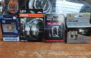
Finding Out the Issue with Bulbs
More modern vehicles are all about sensors, warnings, and messages. The most common way a CANbus system will check if a bulb is working or not is to measure the resistance on the circuit. All the vehicles are checking for the characteristics of a normal filament bulb. One of the core selling points of an LED bulb is the lower power draw.
Who doesn’t want an extra bit of fuel saving, especially with the likes of caravans and motor homes.
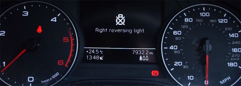
Less power, produced with an extra bit of fuel saving means more resistance. So your vehicle CANbus system is going to see something it’s not expecting and give a simple warning light illuminating or an actual written message. In some cases, it will even cut the power to that circuit, meaning your perfectly good LED bulb fails to illuminate. The problem with the dreaded CANbus error codes includes the false positives created with aftermarket products such as LED bulbs.
Ways to Add the Resistance
There are two main ways to overcome this problem. The first and simplest solution is to fit a CANbus compatible bulb with a direct replacement for your existing bulbs. In 95% of cases, that will be enough to overcome the issue. However, some vehicles can be particularly fussy and still throw up an error. The issue is with the amount of resistance that would need to be put into a bulb for it to match a filament bulb. The resistor would simply be too big and too hot with current technology. The heat from this resistor would probably cause it to fail fairly instantly. Therefore, the manufacturers can only try and get as close as they can and hope it falls within the required levels.
Materials Needed
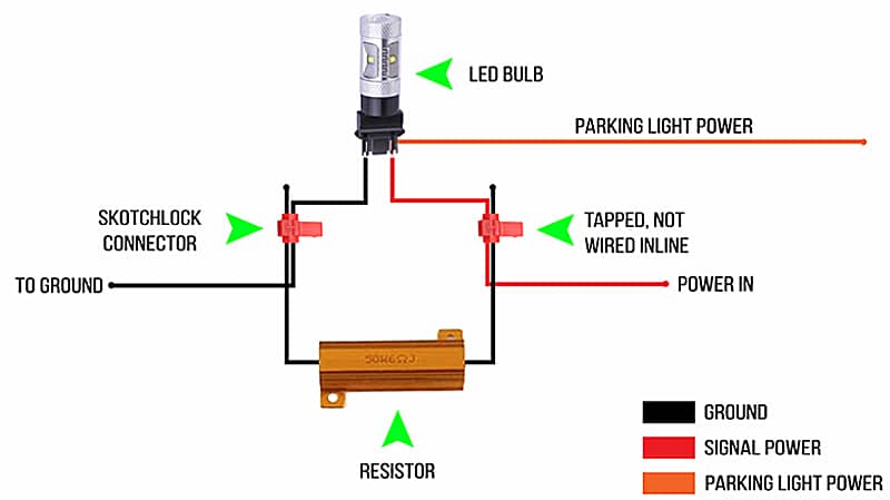
In cases where you simply have a super fussy vehicle and even a CANbus LED bulb doesn’t cut it, we have to move on to our second option and add the resistance another way. This is where resistor kits come in. For each light you’ll need an anti-flicker resistor and two skotchlock connectors. In the case of turn signals, you’ll need four resistors and eight connectors to accommodate the two front signals and two rear signals.
Wires Specification
You’ll need to identify the wires you’ll be working with. Since wire colors vary from vehicle to vehicle, the best way to identify which is which is by referring to the auto manufacturers wiring diagram. If you don’t have access to a wiring diagram, you can use a multimeter to identify the wires.
 Chris Robson Auto Mechanic
Pro Tip: In this identification process you are concerned with locating the ground wire and power wire, for two wire systems. And the ground, power and parking lot power wire, for three wire systems, such as in a turn signal application.
Manufacturers usually use dark or neutral colors for ground, including black and brown, and hot colors for power, such as orange and red. You may encounter a three-wire configuration on your vehicle, especially in the case of turn signals. One wire will be ground, one will be power to the signal, and one will be power to the parking light.
Do not apply the resistor to the parking light lead under any circumstances. This will lead to overheating and failure. For the purposes the installation, deal only with the ground wire and the signal wire.
Creating Parallel Circuit
Connect a resistor onto a part of the bodywork with the bulb to create a parallel circuit, and that will help with a bit of heat dissipation. It supplies the LED bulb with enough power to energize, but the resistor still draws the same amount of power equivalent to a halogen bulb. It’s also not touching anything, any kind of soft plastics.
For three wire systems, bridging the connection between the bulb and the resistor is the same. You just have to keep the parking light lead out of the circuit.
Wires Connection
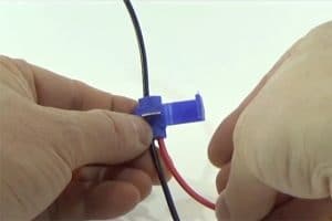
Then take the resistor wire. Connect one leg of the resistor to one of the wires, and the other leg to the other wire. That’s called connecting in parallel. Just take one of the wires, and poke it through the hole in the bottom. Up to the natural stop, put it in place, and then take the metal splice, fold it over, and push that down into place with the help of a set of pliers.
Give a connected leg a little tug to make sure that it’s fully spliced in. If it’s not, these do unlatch, and you can redo them. You just repeat the process for the second one. You will have one resistor connected across in parallel to the bulb holder, and that will add the correct resistance into the circuit.

So I recently bought a Jeep Sahara JL and want to up grade the headlights and fogs! I keep reading different things I to go with a LED bulb for both! I was thinking about the GTR ultra 2s .. will I need decoders?